Specifications
- Output Mode: UART 115200
- Output Interface: LVTTL (3.3V)
- Protocol: Micolink/Mavlink/MSP
- Output Rate: 100Hz
- Firmware Supported: Ardupilot/PX4/INAV/FMT
- TOF Range: 8m@90% reflectance/600Lux; 5m@90% reflectance/60KLux;
Center Wavelength: 850nm
Emitting Half Angle: 3 °
- Dead Zone: 2cm
- Ranging Accuracy: 4cm(<2m@90% reflectance);2%(>2m@90% reflectance)
- Optical Flow FOV: 42 °
- Max Speed Measurement: 7m/s@1m height
- Ambient Light Demand of Optical Flow: >60Lux
- Optical Flow Working Distance: >8cm
- Light source: LED
- Power Consumption: 500mW
- Supply voltage: 5V
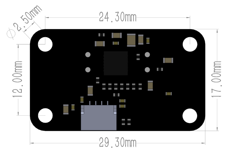
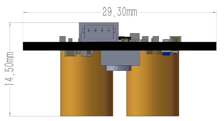
Physical


Micolink
The micolink is a lightweight protocol customized by MicoAir Tech, prepared for developers who are ready to write their own code to read sensor data.
Decoding Micolink Messages from MTF-01 – MicoAir Tech

MicoAssitant software can used for configure protocol or other parameter of MTF-01.
Download it from here.
When you don’t have a USB-TTL module, you may refer to this tutorial:
Configure MTF-01 Sensor By Using Ardupilot’s Serial Passthrough Function
Protocols
MTF-01 module integrated with multiple protocols?include?
- Micolink — a custom protocol, can support FMT
- MSP — support INAV
- Mavlink_APM — the mavlink protocol that can support Ardupilot
- Mavlink_PX4 — the mavlink protocol that can support PX4
Set up protocol by using MicoAssistant
- Step1 : Connect the MTF-01 to PC by using the USB to TTL module.
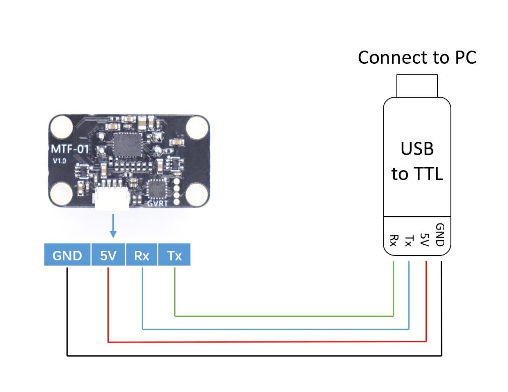
- Step2: Open the windwos device manager and check if the USB module has been recognized.
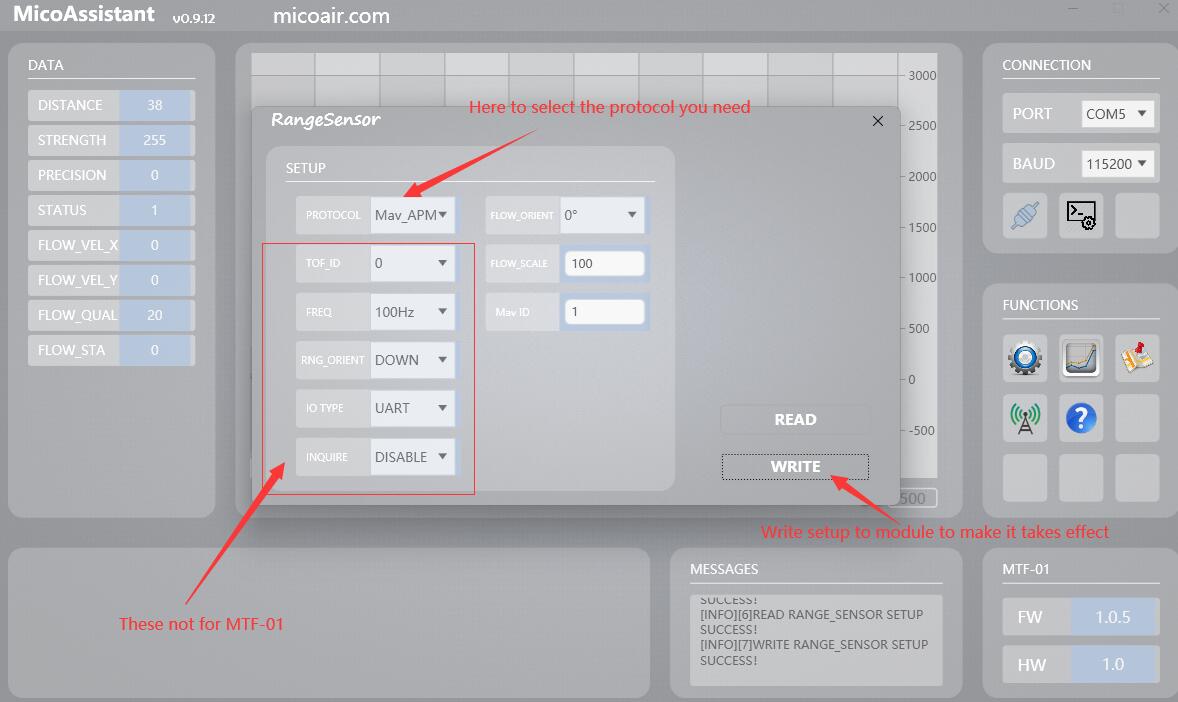
- Step3: Open the MicoAssistant software, select the correct COM in the upper right corner, baudrate should be 115200, and then the connection icon.

- Step4: If the MTF-01 has been successfully connected, the software will recognize it, and will output some messages and display the firmware version in the lower right corner. Then you can click the “SETUP”(gear) icons to open the setup page, it will happens nothing if there is any wrong with the connection, and you should check the previous
- Steps5: Select the protocol you want to use in the setup page, and then click the write button, the output protocol of the module will be successfully modified, and the software message box should display a message that the setting is successful.
Notice
The MicoAssistant software may crash in some language versions of Windows systems. You can try using the “no_chart” version.


